Building an 8-bit addition calculator with circuits

< change language
I have a childhood friend that had very interesting toys... He used to play around with circuits, multimeters, LED lights, small batteries, etc. I loved going to his house and watch him play with all that. That is probably why I find circuits (in their basic form) very interesting: the current flowing and the logic gates operating on the circuits and whatnot.
Because of that, in this post I will show you how to build an 8-bit addition calculator just with circuits! For that I will be using logic.ly, a circuits simulator that I can run in my browser.
The best way to go about this is by starting with small components and then using a nice feature of logic.ly, which enables one to create "integrated circuits": it takes one circuit we created and transforms it into a single piece.
Of course that before anything else one must know how to add two numbers in binary. It is essentially the same as in with decimal numbers, except that $1 + 1 = 10$ now. To create an addition calculator, we will develop a circuit that adds two numbers bit by bit and that takes care of carries from one place to the other.
The image in the beginning of the post is a circuit that adds two bits $A$ and $B$ together. The result is in $S$ and the $Cout$ light bulb represents the carry digit we may get. This small circuit could be used to add the least significant digits in a sum, storing the least significant digit of the result in $S$ and then signaling if there is any carry in $Cout$.
The idea will be to create a circuit that adds two bits of the same significance (possibly taking a carry bit from the previous operation) and then returning both the resulting bit and a possible carry digit.
Let us start by understanding how one comes up with the first circuit shown, a half adder as it is called in electronics. To do that we will summarize the possible combinations of input bits $A, B$ in a table, together with the results of adding them:
\[ \begin{array}{|c|c|c|c|} \hline A & B & S & Cout\\ \hline 0 & 0 & 0 & 0\\ \hline 0 & 1 & 1 & 0\\ \hline 1 & 0 & 1 & 0\\ \hline 1 & 1 & 0 & 1\\ \hline \end{array} \]
From the table above one can see clearly that $S$ should be $1$ only when there is exactly one input equal to $1$ and $Cout$ should be $1$ only when both inputs are equal to $1$; this means that $S = A\stackrel{\cdot}{\vee}B$ and $Cout = A\wedge B$ (the symbol $\stackrel{\cdot}{\vee}$ is the exclusive disjunction, also known as XOR).
The next step is creating a circuit that has three inputs $A$, $B$ and $Cin$, which represent two bits of the same significance and a carry bit from a least significant calculation (respectively) and returns the resulting bit $S$, as well as a carry digit $Cout$. If we build this, we will get a full adder. How does one do it?
First we notice that $S$ will only be $1$ if: all three input bits are $1$ or only one input bit is $1$. We already know if only one of $A$, $B$ is $1$, in which case we want $Cin$ to be $0$. If $A$,$B$ are both $1$ or both $0$, we want $Cin$ to be $1$. Joining the two we can write $$S = [(A\stackrel{\cdot}{\vee}B) \wedge \lnot Cin] \vee [\lnot(A \stackrel{\cdot}{\vee} B) \wedge Cin]$$ Carefull inspection shows that this can be simplified to $$S = (A \stackrel{\cdot}{\vee} B) \stackrel{\cdot}{\vee} Cin$$ In fact, that is exactly what is written in the first expression: $S$ is $1$ whenever only one of $A \stackrel{\cdot}{\vee} B$, $Cin$ is $1$.
Having computed $S$ we are only left with computing $Cout$. We know that there will be a carry digit if at least two of the input bits are $1$. We already know when $A$ and $B$ are both $1$, so the other alternative is when only one of $A, B$ is $1$ and $Cin$ is also $1$, hence $$Cout = (A \wedge B) \vee ([A \stackrel{\cdot}{\vee} B] \wedge Cin)$$ We use the exclusive disjuntion instead of the disjunction on the right because that allows us to reuse information we already have. If we put everything together in a circuit, we get this:

Because all switches are turned off, we are computing $0 + 0$ which is $0$, as the two light bulbs show.
If we compare the symbols of the logic gates with the first image in the post, we see two XOR gates on the top, an OR gate on the bottom right (the XOR gates are equal to the OR gate with an extra line on the left) and two AND gates centred on the bottom of the image.
With the full adder in place, we aggregate everything and use logic.ly's feature of creating an integrated circuit which creates this piece:

This piece is a compact representation of the circuit I showed above. With four of these it is straightforward to create a 4-bit addition calculator: a calculator that takes two 4-bit numbers and returns its result:
The image above shows the calculator computing the sum $5 + 12 = 17$. Notice how we plug in a constant $0$ on the first $Cin$ and how the last $Cout$ is connected to the fifth light bulb. Renaming the switches and plugging a switch into the first $Cin$ allows me to create yet another integrated circuit that already adds 4-bit numbers! This is how the modified circuit will look like, before creating the IC:

With two of those, one can create an 8-bit addition calculator, as shown below:

In this particular screenshot, the calculator is computing the sum $73 + 37 = 110$.
And this is it. In the future I might try to build the calculator with actual physical parts, who knows? If you try logic.ly and create something cool, consider sharing it in the comments! Does anyone have the patience to build a 16-bit number adder? Or maybe a circuit that performs subtraction?
Because of that, in this post I will show you how to build an 8-bit addition calculator just with circuits! For that I will be using logic.ly, a circuits simulator that I can run in my browser.
The best way to go about this is by starting with small components and then using a nice feature of logic.ly, which enables one to create "integrated circuits": it takes one circuit we created and transforms it into a single piece.
Of course that before anything else one must know how to add two numbers in binary. It is essentially the same as in with decimal numbers, except that $1 + 1 = 10$ now. To create an addition calculator, we will develop a circuit that adds two numbers bit by bit and that takes care of carries from one place to the other.
The image in the beginning of the post is a circuit that adds two bits $A$ and $B$ together. The result is in $S$ and the $Cout$ light bulb represents the carry digit we may get. This small circuit could be used to add the least significant digits in a sum, storing the least significant digit of the result in $S$ and then signaling if there is any carry in $Cout$.
The idea will be to create a circuit that adds two bits of the same significance (possibly taking a carry bit from the previous operation) and then returning both the resulting bit and a possible carry digit.
Let us start by understanding how one comes up with the first circuit shown, a half adder as it is called in electronics. To do that we will summarize the possible combinations of input bits $A, B$ in a table, together with the results of adding them:
\[ \begin{array}{|c|c|c|c|} \hline A & B & S & Cout\\ \hline 0 & 0 & 0 & 0\\ \hline 0 & 1 & 1 & 0\\ \hline 1 & 0 & 1 & 0\\ \hline 1 & 1 & 0 & 1\\ \hline \end{array} \]
From the table above one can see clearly that $S$ should be $1$ only when there is exactly one input equal to $1$ and $Cout$ should be $1$ only when both inputs are equal to $1$; this means that $S = A\stackrel{\cdot}{\vee}B$ and $Cout = A\wedge B$ (the symbol $\stackrel{\cdot}{\vee}$ is the exclusive disjunction, also known as XOR).
The next step is creating a circuit that has three inputs $A$, $B$ and $Cin$, which represent two bits of the same significance and a carry bit from a least significant calculation (respectively) and returns the resulting bit $S$, as well as a carry digit $Cout$. If we build this, we will get a full adder. How does one do it?
First we notice that $S$ will only be $1$ if: all three input bits are $1$ or only one input bit is $1$. We already know if only one of $A$, $B$ is $1$, in which case we want $Cin$ to be $0$. If $A$,$B$ are both $1$ or both $0$, we want $Cin$ to be $1$. Joining the two we can write $$S = [(A\stackrel{\cdot}{\vee}B) \wedge \lnot Cin] \vee [\lnot(A \stackrel{\cdot}{\vee} B) \wedge Cin]$$ Carefull inspection shows that this can be simplified to $$S = (A \stackrel{\cdot}{\vee} B) \stackrel{\cdot}{\vee} Cin$$ In fact, that is exactly what is written in the first expression: $S$ is $1$ whenever only one of $A \stackrel{\cdot}{\vee} B$, $Cin$ is $1$.
Having computed $S$ we are only left with computing $Cout$. We know that there will be a carry digit if at least two of the input bits are $1$. We already know when $A$ and $B$ are both $1$, so the other alternative is when only one of $A, B$ is $1$ and $Cin$ is also $1$, hence $$Cout = (A \wedge B) \vee ([A \stackrel{\cdot}{\vee} B] \wedge Cin)$$ We use the exclusive disjuntion instead of the disjunction on the right because that allows us to reuse information we already have. If we put everything together in a circuit, we get this:
Because all switches are turned off, we are computing $0 + 0$ which is $0$, as the two light bulbs show.
If we compare the symbols of the logic gates with the first image in the post, we see two XOR gates on the top, an OR gate on the bottom right (the XOR gates are equal to the OR gate with an extra line on the left) and two AND gates centred on the bottom of the image.
With the full adder in place, we aggregate everything and use logic.ly's feature of creating an integrated circuit which creates this piece:
This piece is a compact representation of the circuit I showed above. With four of these it is straightforward to create a 4-bit addition calculator: a calculator that takes two 4-bit numbers and returns its result:
The image above shows the calculator computing the sum $5 + 12 = 17$. Notice how we plug in a constant $0$ on the first $Cin$ and how the last $Cout$ is connected to the fifth light bulb. Renaming the switches and plugging a switch into the first $Cin$ allows me to create yet another integrated circuit that already adds 4-bit numbers! This is how the modified circuit will look like, before creating the IC:
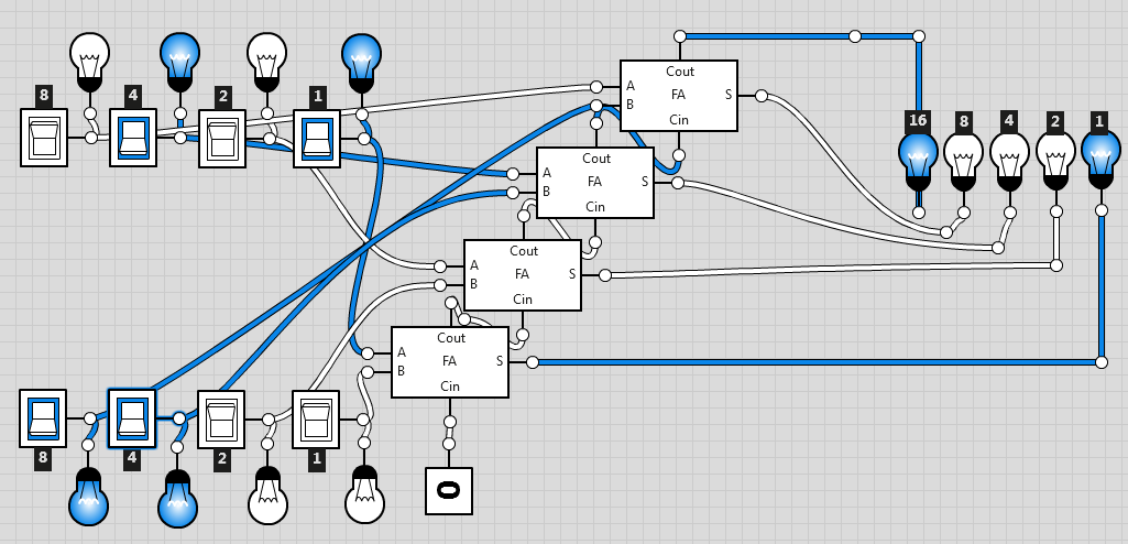
With two of those, one can create an 8-bit addition calculator, as shown below:
In this particular screenshot, the calculator is computing the sum $73 + 37 = 110$.
And this is it. In the future I might try to build the calculator with actual physical parts, who knows? If you try logic.ly and create something cool, consider sharing it in the comments! Does anyone have the patience to build a 16-bit number adder? Or maybe a circuit that performs subtraction?
Tenho um amigo de infância que tinha uns brinquedos super engraçados... Ele costumava brincar com circuitos, multímetros, LEDs, pilhas, etc. Adorava ir a casa dele e vê-lo mexer naquilo tudo e ele costumava ensinar-me qualquer coisinha. É provavelmente por causa disso que circuitos elétricos me fascinam tanto: como as portas lógicas conseguem fazer tudo o que fazem quando bem conjugadas.
É por causa desse fascínio que, neste post, vou mostrar como construir uma calculadora (que só sabe somar) com circuitos! Para isso vamos usar o logic.ly, um simulador de circuitos que se pode correr no browser.
A melhor maneira de fazer isto é começando com circuitos mais pequenos e depois usar uma funcionalidade do logic.ly que permite compactar circuitos em peças únicas.
Claro que antes de começar a montar seja o que for é preciso saber somar em binário. É essencialmente igual a fazer somas no sistema decimal, mas agora $1 + 1 = 10$. Para criar a calculadora vamos desenvolver um circuito que os soma bit a bit, tratando também do "e vai $1$", que chamamos "carry" em inglês (lamentavelmente não arranjei nenhuma outra designação para este "e vai $1$", e portanto é esta a designação que vou usar durante o post).
A imagem no início do post é de um circuito que soma dois bits $A$ e $B$. O bit resultante fica em $S$ e o "e vai $1$", se houver, fica em $Cout$, sinalizado pela lâmpada. Este circuito em particular pode ser usado para somar os dois dígitos menos significantes, i.e. pode ser usado para obter o dígito mais à direita numa soma.
A ideia vai ser criar um circuito que vá calculando cada bit do resultado, olhando para os bits respetivos do input, e que vá transferindo os "e vai $1$" sempre que necessário.
Vamos começar por entender como criar o primeiro circuito de todos, a que chamamos half adder em eletrónica. Para isso vamos começar por sumarizar todas as combinações que podemos ter no input para $A$ e $B$ e sistematizá-las numa tabela, juntamente com os resultados pretendidos (que obtemos se somarmos $A$ com $B$):
\[ \begin{array}{|c|c|c|c|} \hline A & B & S & Cout\\ \hline 0 & 0 & 0 & 0\\ \hline 0 & 1 & 1 & 0\\ \hline 1 & 0 & 1 & 0\\ \hline 1 & 1 & 0 & 1\\ \hline \end{array} \]
Pela tabela em cima podemos ver que $S$ deve ser $1$ quando apenas um dos inputs é igual a $1$ e $Cout$ deve ser $1$ quando os dois inputs são $1$; isto significa que $S = A \stackrel{\cdot}{\vee} B$ e $Cout = A\wedge B$ (o símbolo $\stackrel{\cdot}{\vee}$ é a disjunção exclusiva, também conhecida como XOR).
O próximo passo é criar um circuito com três inputs $A$, $B$ e $Cin$, que representam respetivamente dois bits dos números que queremos somar e um possível "e vai $1$" do passo anterior, e que devolve o bit resultante em $S$, bem como o possível "vai $1$" desta adição em $Cout$. Se construirmos isto obtemos um full adder. Como o fazemos?
Primeiro notamos que $S$ só é $1$ se: ou os três bits de input forem $1$ ou se apenas um bit de input for $1$. Já temos como saber se apenas $A$ ou apenas $B$ são $1$, caso em que queremos que $Cin$ seja $0$. Se $A$ e $B$ têm o mesmo valor, então precisamos que $Cin$ seja $1$. Juntando estas duas premissas obtemos $$S = [(A\stackrel{\cdot}{\vee}B) \wedge \lnot Cin] \vee [\lnot(A \stackrel{\cdot}{\vee} B) \wedge Cin]$$ Se olharmos com atenção percebemos que podemos simplificar esta expressão para $$S = (A \stackrel{\cdot}{\vee} B) \stackrel{\cdot}{\vee} Cin$$ De facto, isto é exatamente o que está escrito na primeira expressão: $S$ é $1$ sempre que apenas um de $A \stackrel{\cdot}{\vee} B$ ou $Cin$ tenha o valor $1$.
Tendo calculado $S$, falta-nos calcular $Cout$. Sabemos que "vai $1$" se dois ou mais dos bits de input forem $1$. Já sabemos quando é que $A$ e $B$ são os dois $1$, portanto só falta ver quando apenas um de $A$, $B$ é $1$ e $Cin$ também é $1$, de onde vem $$Cout = (A \wedge B) \vee ([A \stackrel{\cdot}{\vee} B] \wedge Cin)$$ Usamos a disjunção exclusiva em vez da disjunção ("normal") porque desse modo podemos reutilizar uma porta lógica que já temos no circuito. Se montarmos tudo, obtemos o seguinte:
Porque todos os interruptores estão desligados, estamos a calcular a soma $0 + 0$ que é, obviamente, $0$, tal como as duas lâmpadas desligadas mostram.
Se compararmos estas portas lógicas com as da primeira imagem do post, vemos que as duas portas usadas no topo são portas XOR, vemos que temos uma porta OR em baixo à direita (com a mesma forma das portas XOR, a diferença é que a porta OR tem um traço a menos) e duas portas AND centradas na parte de baixo da imagem.
Com este circuito feito, compactamos tudo num circuito integrado (uma funcionalidade do logic.ly) para obter a seguinte peça:
Esta peça não é mais do que uma representação compacta do circuito em cima. Com quatro destas peças é facílimo construir uma calculadora que some dois números de 4 bits:
A imagem mostra-nos o cálculo $5 + 12 = 17$. Note-se que em baixo usámos um sinal constante igual a $0$ como primeiro $Cin$ e que ligámos o último $Cout$ à quinta lâmpada, a de maior significância (16). Se mudarmos os nomes dos interruptores e se ligarmos um interruptor ao primeiro $Cin$, podemos criar outro novo circuito integrado! Esta foi a modificação que fiz para poder criar o circuito integrado:
Com dois desses circuitos integrados maiores faz-se uma calculadora que some dois números de 8 bits, como se vê de seguida:
Nesta captura de ecrã em particular a calculadora computou a soma $73 + 37 = 110$.
Está feito! No futuro sou capaz de tentar construir fisicamente esta calculadora com as portas lógicas mesmo, só porque sim. Se forem experimentar o logic.ly e se fizerem alguma coisa engraçada, partilhem-na nos comentários! Será que alguém tem paciência para fazer um circuito que some números de 16 bits? Ou talvez que faça subtrações?
- RGS

